What Can Cause PF Softstarter Line Faults F41, F42 & F43?
Question:
My PF softstarter has a Line fault F41, F42 or F43. How do I know if this is caused by bad line / faulty load or a suspect PF?
Answer:
While the literature refers to these faults as "Line Loss", the causes are not just restricted to anomalies with the AC input line. The occurrence of the fault merely indicates that there is an anomaly with that particular phase, so could equally be due to the load or even the PF itself. Provided that you are seeing repeated occurrences of the same fault number, it is possible to carry out further checks to isolate the cause of the fault. These are discussed below. Our example assumes we have seen continual occurrences of fault F2, so indicates an anomaly with phase B.
ALL POWER MUST BE REMOVED PRIOR TO CONDUCTING EACH TEST
Test for healthy line (3-phase AC input)
- Make a note of input phase rotation, for example L1 = RED, L2 = YELLOW, L3 = BLUE.
- Disconnect all three input conductors.
- Now move each conductor one phase "to the right", ensuring the conductor that was connected to L3 is now connected to L1. Our example would now give L1 = BLUE, L2 = RED, L3 = YELLOW. This procedure ensures that the phase rotation remains correct, so the motor will rotate in the original direction.
- Power the unit up again, and attempt to run the motor.
- If the same fault number (F2) appears, then the AC input line is unlikely to be the cause, in which case further testing, below, should be conducted.
- If the fault number has changed (most likely to F3, as the suspect conductor is now connected to L3) then the AC line should be suspected.
Test for healthy load
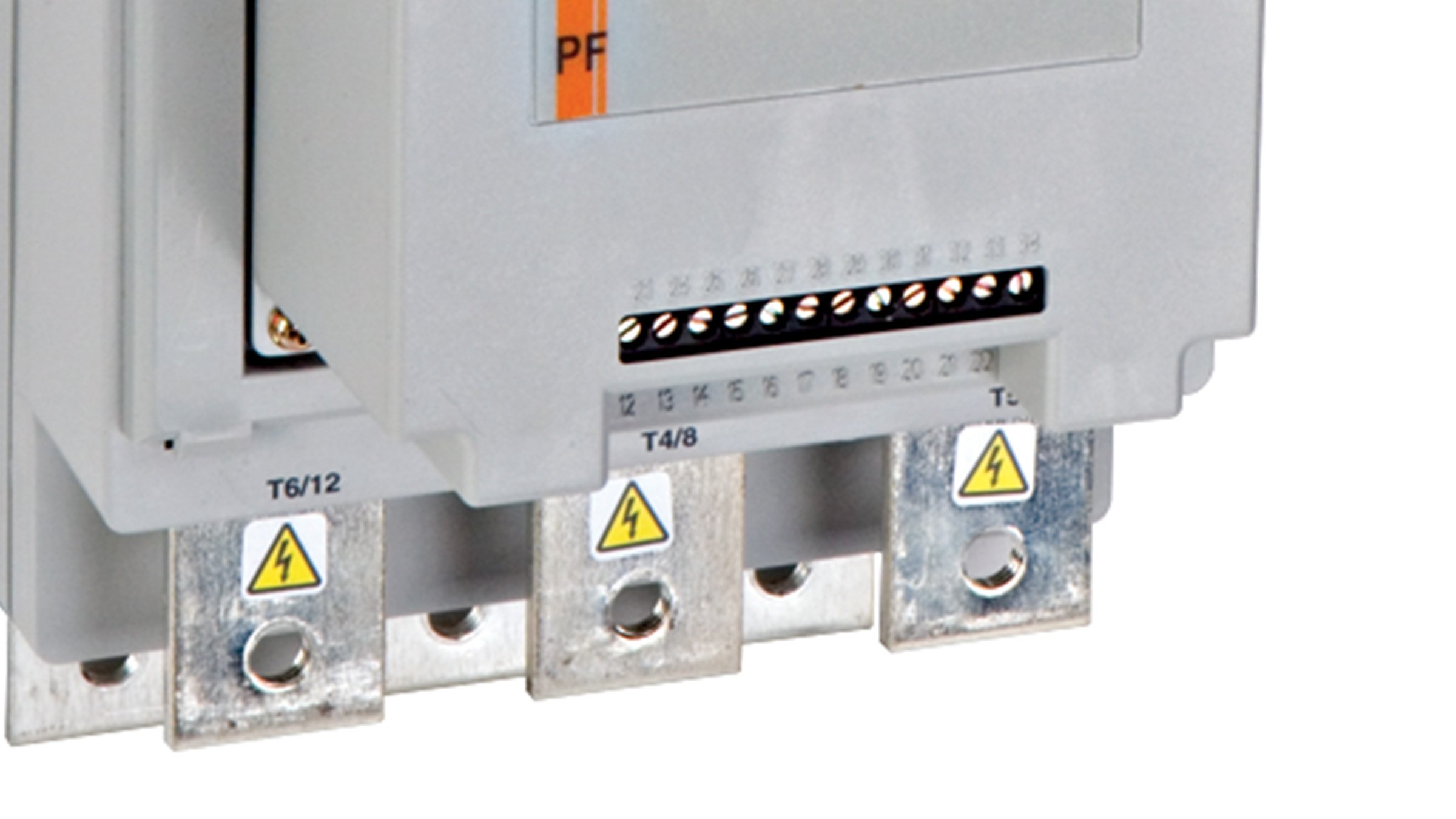
- Make a note of output phase rotation, for example T1 = RED, T2 = YELLOW, T3 = BLUE.
- Disconnect all three output conductors.
- Now move each conductor one phase "to the right", ensuring the conductor that was connected to T3 is now connected to T1. Our example would now give T1 = BLUE, T2 = RED, T3 = YELLOW. This procedure ensures that the phase rotation remains correct, so the motor will rotate in the original direction.
- Power the unit up again, and attempt to run the motor.
- If the same fault number (F2) appears, then the load is unlikely to be the cause, in which case further testing, below, should be conducted.
- If the fault number has changed (most likely to F3, as the suspect conductor is now connected to T3) then the load should be suspected.
Test for healthy PF
- Using an ohmmeter, measure the resistance between the line and load terminals of each phase on the controller. (L1-T1, L2-T2, & L3-T3).
- The resistance should be greater than 10,000 ohms.
If none of these tests prove to be conclusive, then contact Sprecher + Schuh Technical Support for further assistance.
For additional information please contact your nearest authorized distributor, sales representative, or call our customer service or technical support lines.