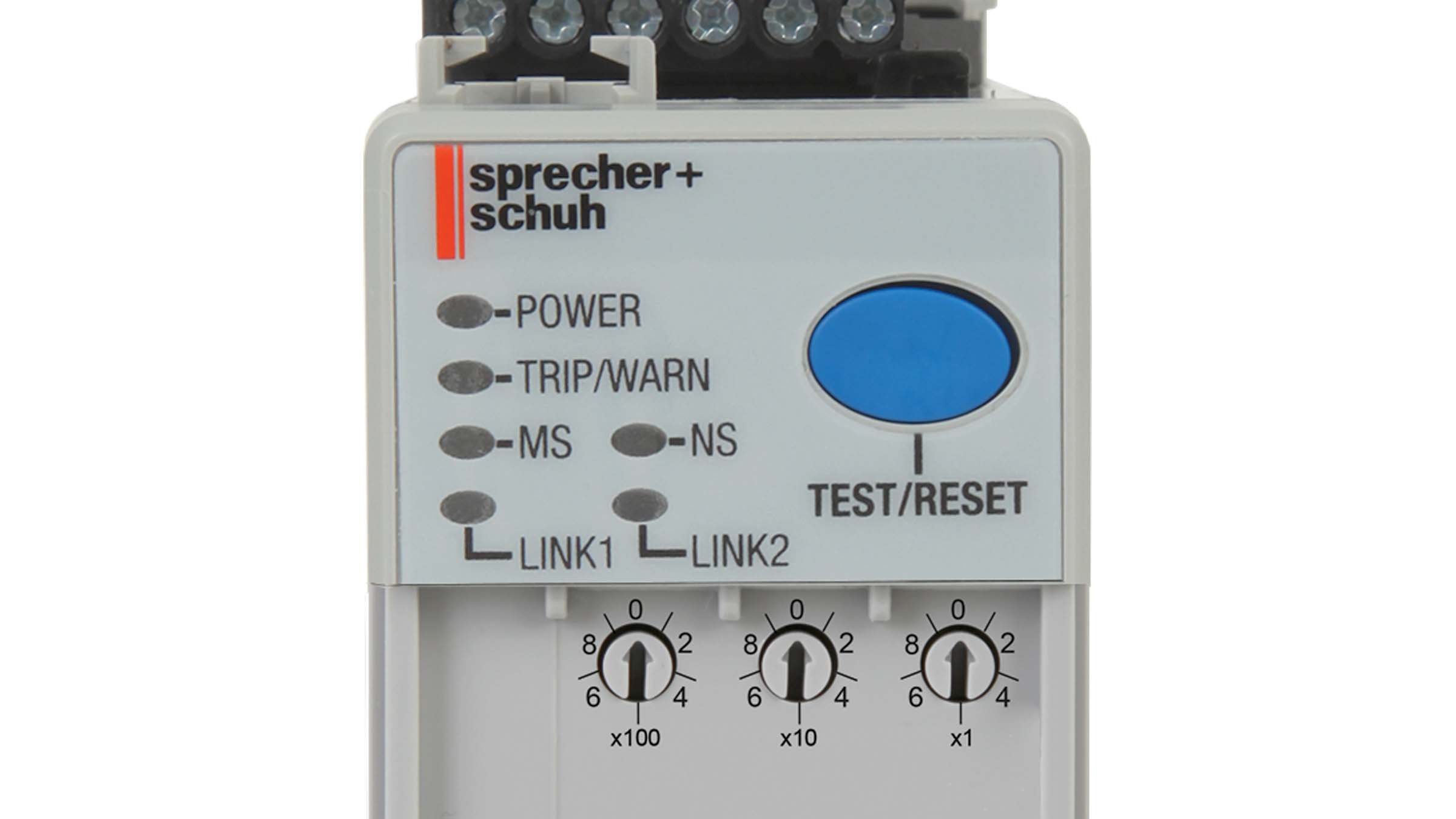
CEP9 Overload Relay Device Modes And Dial Functions
Question:
What are the different device modes and the rotary dial functions of the CEP9 Electronic Overload Relay?
Answer:
The CEP9 Electronic Overload Relay has four device modes to validate configuration of the device and limit when a user can configure the overload relay, perform a firmware update, and issue commands. These modes are:
- Administration Mode
- Operation Mode
- Run Mode
- Invalid Configuration Mode
The CEP9-ECM-ETR Electronic Overload Relay EtherNet/IP Communication Module comes with three node address selection switches that allow the user to select the last octet for the IP address 192.168.1.xxx.When the node address selection switches are set to a value greater than 255 (excluding 888), the IP address is set to DHCP Enabled or programmed for a static IP address.
Administration Mode:
As a security precaution the embedded web server of the CEP9 EtherNet/IP Communication Module is disabled by default. To temporarily enable the web server to make it permanently available, the user must enter into Administration Mode. To do this, set the rotary dials located underneath the front cover of the CEP9 EtherNet/IP Communication Module to 000 and cycle power. The device will then go online with the IP Address used at the time of the previous start-up.
Operation Mode:
Turn the rotary switches to factory default position 999 (DHCP Mode) and cycle power to restore EtherNet/IP. The MS (Module Status) LED on the CEP9 EtherNet/IP communications will blink green. When the node address selection switches are set to a value greater than 255 (excluding 888), the IP address is set to DHCP Enabled or programmed for a static IP address via web browser or software. You can now set the last octet (192.168.1.xxx) of the IP Address to a valid node address between 001 and 254.
Operation Mode is a standby mode for the CEP9 Electronic Overload Relay in which the CEP9 is ready to protect an electric motor and no electrical current has been detected. Users can modify configuration parameters, upgrade firmware and issue commands if the appropriate security policies are enabled. The Power LED on the Communication Module and Operator Stations will be flashing green and bit 14 in Device Status 0 (Parameter 20) is set to 1 when the device is in Operation Mode.
Run Mode:
Run Mode is an active mode for the CEP9 Electronic Overload Relay in which the CEP9 is sensing electrical current and is actively protecting an electric motor. Only non-motor protection configuration parameters can be modified if the appropriate security policies are enabled. The Power LED on the Communication Module and Operator Stations will be solid green and bits 3, 4, and/or 5 in Device Status 0 (Parameter 20) are set to 1 when the device is in Run Mode.
Invalid Configuration Mode:
Invalid Configuration Mode is an active mode for the CEP9 Electronic Overload Relay in which the CEP9 is in a tripped state due to invalid configuration data. Invalid Configuration Parameter (Parameter 38) indicates the parameter number that is causing the fault. Invalid Configuration Cause (Parameter 39) identifies the reason for Invalid Configuration Mode. The Trip/Warn LED on the Communication Module and Operator Stations will be flashing a pattern of red, 3 long and 8 short blinks, and bits 0 and 2 in Device Status 0 (Parameter 20) are set to 1 when the device is in Invalid Configuration Mode.
Restore Factory Defaults:
Turn all rotary switches to 888 and cycle power on the device to restore factory defaults. The MS (Module Status) LED on the CEP9 EtherNet/IP communications will blink red indicating that a factory default reset has occurred.
For additional information please contact your nearest authorized distributor, sales representative, or call our customer service or technical support lines.
