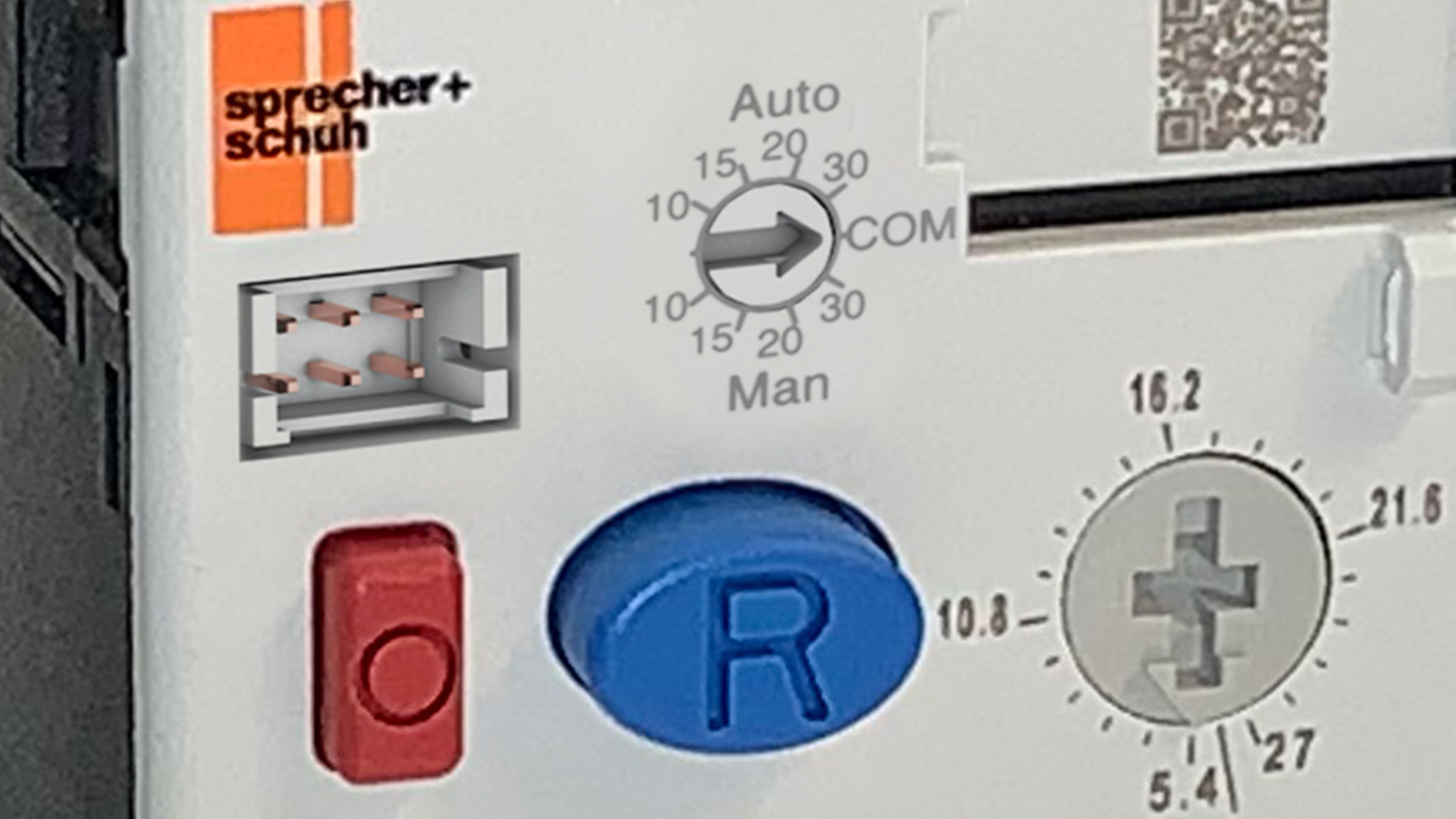
CEP7 Overload Relay Testing Procedures
Question:
What procedure can be used to test the phase loss or overload protection on a CEP7 overload relay?
Answer:
Our normal production test procedure is not something that a customer could easily duplicate. However, a basic on-site test can be run following the examples below (assuming that the motor is not running at the minimum FLA of the overload):
Overload Protection Test:
- Measure the normal motor running current (i motor).
- Turn off the motor and let it cool for about 10 minutes.
- Calculate the following ratio: i (motor) / i (overload min FLA).
For example, if i (motor) = 3.0A, and the customer is using a 1-5A overload, i (overload min FLA) is 1 and the ratio is 3. If the ratio is less than 1.2, this test cannot be run. For best results the shortest test times are obtained when the ratio is 2.0 or greater. - Set the overload to its minimum FLA and turn on the motor.
- Wait for the overload to trip. The trip time should be within the range defined by the trip curves on the overload instruction sheet for the ratio calculated. The trip time should be close to the cold trip time defined on the curves as shown on the CEP7 instruction sheet.
Phase Loss Test:
If a phase loss test is desired, the customer may install a suitably-rated normally closed (NC) contact block or NC contactor in series with one of the motor phases. To run the test perform the following steps:
- Turn the FLA dial back to its proper setting and let the motor run for at least 5 minutes
- Open the contact(or) while the motor is running and start a timer
- The overload should trip in around 3 seconds, or within 10 seconds maximum. In order to prevent damage to the motor, under no circumstances should the customer simulate a phase loss in this manner for longer than 10 seconds.
The CEP7 phase loss detection is designed to operate under the following conditions:
- The CEP7 overload will trip on a phase loss condition once the current in one of the legs drops below 30% of the FLA dial setting.
- The incoming 3-phase power takes the current and makes a voltage signal per phase on it. Then it combines the voltage values of the phases. These make a sinusoidal wave representing the status of the phases. When the value of the wave drops to a certain threshold, the relay trips on phase loss.
- The CEP7 also uses TCU (Thermal capacity memory) to detect phase loss. When a phase loss is present, the TCU elevates rapidly from the normal percent around 65-80% very quickly to 150-160%, for example. When initializing, the TCU starts at 0%, and if it detects a phase loss it will go up to the 65-80%s’. Therefore, at start up the CEP7 will not be able to detect a phase loss. It will trip on phase loss after the TCU gets near to full capacity.
Other important items to make note of for a Phase Loss testing procedures are the following:
- the overload must be fully powered up, and
- the thermal memory must be above about 70%
In order to guarantee that both of these conditions are met, it is a good idea to run the motor at (or near) 100% of the overload FLA setting for about 5 minutes or more before running the phase loss test. If you do this, the overload will trip for phase loss in about 3 seconds. Conversely, if you try to run a phase loss test on a "cold" overload, you will find that it will take a while, perhaps 1 to 2 minutes worst case, because of the need to satisfy the conditions noted above.
